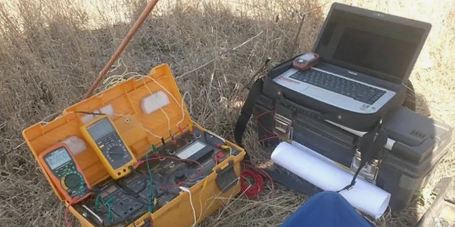
A reinforced yellow Pelican case holds the core of the operation—a Syscal Kid Switch 24 resistivity meter with stainless steel electrodes and heavy-gauge copper cabling rolled onto portable spools. Field crews working the Fort Worth Prairie deploy these arrays across limestone benches and floodplain clays in the Trinity River watershed, injecting a controlled DC current into the ground and measuring the resulting potential drop across a Wenner or Schlumberger spread. The resistance values recorded at each electrode spacing are inverted via least-squares algorithms to produce a 1D layered resistivity model, which the geophysicist then correlates with Fort Worth’s known stratigraphy: Goodland-Walnut formations over Glen Rose limestone, with alluvial cover in the Clear Fork valley. When penetration beyond 30 meters is needed for groundwater basin delineation, the seismic refraction method provides complementary P-wave velocity profiles that help distinguish saturated from dry limestone horizons.
A vertical electrical sounding resolves the depth to bedrock within 10 percent of the electrode spread length when the resistivity contrast exceeds a factor of three.
Technical details of the service in Fort Worth
Risks and considerations in Fort Worth
The Eagle Ford Shale underlying much of southwestern Fort Worth exhibits electrical resistivity values between 5 and 30 Ω·m when saturated, which masks the resistivity contrast with overlying alluvial clays and makes bedrock depth interpretation ambiguous without borehole control. In these low-resistivity environments, the depth of investigation decreases because the current preferentially flows in the conductive near-surface layer, reducing the penetration of the electrical field into deeper strata. A second complication arises in the Meandering Road Creek floodplain, where buried utility corridors and reinforced concrete culverts create cultural noise that distorts the apparent resistivity curve at larger electrode spacings—above AB/2 of 40 meters, the signal-to-noise ratio often drops below 3:1, requiring stacked readings and post-acquisition filtering to recover interpretable data. The team addresses these limitations by acquiring reciprocal measurements at each spacing and discarding any datum where the forward-reverse deviation exceeds 5 percent, a protocol derived from the USGS resistivity surveying manual.
Our services
The electrical resistivity group in Fort Worth operates two resistivity meters with multi-core cables and non-polarizing Cu-CuSO4 electrodes for spontaneous potential monitoring. Sounding programs typically run 4 to 8 stations per day depending on terrain and access, with data processed overnight in Res2DInv and EarthImager software.
Vertical Electrical Sounding (VES) for Stratigraphy & Groundwater
1D resistivity soundings using Schlumberger arrays with AB/2 from 1.5 to 150 meters, processed through Occam inversion to map water table depth, bedrock topography, and clay lens continuity beneath Fort Worth’s alluvial and limestone terrains. Each sounding is tied to a local borehole log when available, and the final model reports layer resistivity, thickness, and interpreted lithology with RMS misfit below 3 percent.
2D Electrical Resistivity Tomography & Contamination Delineation
Multi-electrode profiling with 48 or 72 electrodes at 3- to 5-meter spacing, acquiring dipole-dipole and Wenner-Schlumberger arrays along a single transect. Used for mapping landfill leachate plumes, brine migration from historical oil fields, and saline water intrusion in the Trinity alluvial aquifer. Time-lapse inversion available for monitoring remediation progress over sequential surveys.
Quick answers
What is the typical depth of investigation for a VES survey in the Fort Worth area?
With a Schlumberger array and maximum current electrode spacing AB/2 of 150 meters, the depth of investigation reaches roughly 45 to 60 meters in the Glen Rose limestone, though this decreases to about 25 meters when the near-surface clay is saturated and conductive. The actual depth depends on the resistivity contrast between layers and the signal-to-noise ratio at the site.
How much does an electrical resistivity survey cost in Fort Worth?
Can electrical resistivity distinguish between shale and limestone in the Fort Worth Basin?
The resistivity contrast between the Eagle Ford Shale (5–30 Ω·m) and the underlying Buda Limestone (80–300 Ω·m) is sufficient for discrimination when the shale is not fully water-saturated. However, in the saturated zone below the water table, both formations can exhibit overlapping resistivity ranges, so the interpretation must be constrained by at least one borehole or supplemented with seismic refraction velocity data to reduce ambiguity.