In Fort Worth, the transition from limestone to shale or sandstone happens fast. One lot might probe out solid; the next one hits weathered pockets or solutioned zones that an excavator won't catch until it's too late. That's why we run seismic tomography early. Refraction profiles give us a continuous velocity map across the site, while reflection sections image deeper contacts where a standard boring would miss a dipping boundary. For a warehouse pad near Eagle Mountain Lake last spring, this combination saved the owner two weeks of over-excavation by pinpointing exactly where competent rock started. When the IBC requires site class determination, the same dataset feeds the Vs30 calculation under ASCE 7. We often pair these surveys with MASW profiling for a redundant shear-wave velocity check, and with resistivity imaging where clay seams or perched water might fool a velocity-only interpretation.
A well-shot seismic line doesn't just find rock—it tells you whether that rock can carry the column loads without settlement surprises.
Technical details of the service in Fort Worth
Risks and considerations in Fort Worth
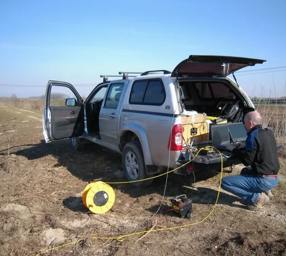
We bring an accelerated weight-drop trailer onto the site. It pounds the ground every few seconds while the geophones record the arrival time of the compression wave. In a Fort Worth subdivision going in on the Woodbine Formation, that thumping is the only thing that reliably separates tight sandstone from the shale lenses that swell and shrink with every rain season. Skip the seismic survey and you're left with a handful of boreholes that tell you what's at five points, not what's between them. We've seen a foundation designed for 3 ksf bear on a shale seam that should have been rated at 1.5 ksf because the boring missed it by fifteen feet. The subsurface risk in Tarrant County isn't just rock depth; it's lateral variability, and only a continuous geophysical method catches it.
Our services
Our Fort Worth seismic tomography work covers the full chain from acquisition to interpretation. The goal is always the same: give the design team a velocity model they can trust.
Refraction microzonation
We shoot multiple intersecting lines to map the top-of-rock surface and identify velocity reversals that indicate weathering or fracturing. Output includes a 3D fence diagram and a contoured bedrock elevation map for the civil engineer.
Reflection profiling for deep structure
When a proposed deep excavation or tunnel needs to know the dip of the Paluxy-Upper Glen Rose contact, we acquire a common-midpoint reflection section and migrate it to produce a true-depth cross-section.
Vs30 and site class determination
Using the MASW or refraction-MASW hybrid approach, we compute the time-averaged shear-wave velocity to 100 ft and assign the ASCE 7 site class. This is mandatory for any Fort Worth structure over three stories.
Rippability and excavation assessment
We correlate the seismic velocity with published rippability charts for Caterpillar D8-D11 dozers so the contractor knows where rock can be ripped and where it needs a hammer.